Rogers 2009 Annual Report Download - page 28
Download and view the complete annual report
Please find page 28 of the 2009 Rogers annual report below. You can navigate through the pages in the report by either clicking on the pages listed below, or by using the keyword search tool below to find specific information within the annual report.-
 1
1 -
2
-
3
-
4
-
5
-
6
-
7
-
8
-
9
-
10
-
11
-
12
-
13
-
14
-
15
-
16
-
17
-
 18
18 -
 19
19 -
 20
20 -
 21
21 -
 22
22 -
 23
23 -
 24
24 -
 25
25 -
 26
26 -
 27
27 -
 28
28 -
 29
29 -
 30
30 -
 31
31 -
 32
32 -
 33
33 -
 34
34 -
 35
35 -
 36
36 -
 37
37 -
 38
38 -
39
-
40
-
41
-
42
-
43
-
44
-
45
-
46
-
47
-
48
-
49
-
50
-
51
-
52
-
53
-
54
-
55
-
56
-
57
-
58
-
59
-
60
-
61
-
62
-
63
-
64
-
65
-
66
-
67
-
68
-
69
-
70
-
71
-
72
-
73
-
74
-
75
-
76
-
77
-
78
-
79
-
80
-
81
-
82
-
83
-
84
-
85
-
86
-
87
-
88
-
89
-
90
-
91
-
92
-
93
-
94
-
95
-
96
-
97
-
98
-
99
-
100
-
101
-
102
-
103
-
104
-
105
-
106
-
107
-
108
-
109
-
110
-
111
-
112
-
113
-
114
-
115
-
116
-
117
-
118
-
119
-
120
-
121
-
122
-
123
-
124
-
125
-
126
-
127
-
128
-
129
-
130
 |
 |

32 ROGERS COMMUNICATIONS INC. 2009 ANNUAL REPORT
MANAGEMENT’S DISCUSSION AND ANALYSIS OF FINANCIAL CONDITION AND RESULTS OF OPERATIONS
retail locations, Cable markets its services and products through
a variety of additional channels, including call centres, outbound
telemarketing, field agents, direct mail, television advertising, its
own direct sales force, exclusive and non-exclusive agents, as well
as through business associations. Cable also offers products and
services and customer service via our e-business website, rogers.
com. The information contained in or connected to our website is
not a part of and not incorporated into this MD&A.
Cable’s Networks
Cable’s networks in Ontario and New Brunswick, with few
exceptions, are interconnected to regional head-ends, where
analog and digital channel line-ups are assembled for distribution
to customers and Internet traffic is aggregated and routed to and
from customers, by inter-city fibre-optic rings. The fibre-optic
interconnections allow the majority of its cable systems to function
as a single cable network. Cable’s two regional head-ends in
Toronto, Ontario and Moncton, New Brunswick provide the source
for most television signals used across our cable systems.
Cable’s technology architecture is based on a three-tiered structure
of primary hubs, optical nodes and co-axial distribution. The primary
hubs, located in each service region, are connected by an inter-city
fibre-optic network carrying television, Internet, network control
and monitoring and administrative traffic. The fibre-optic network
is generally configured in rings that allow signals to flow in and out
of each primary hub, or head-end, through two paths, providing
protection from a fibre cut or other disruption. These high-capacity
fibre-optic networks deliver high performance and reliability and
generally have capacity for future growth in the form of dark fibres
and unused optical wavelengths. Approximately 99% of the homes
passed by Cable’s network are fed from primary hubs, or head-ends,
which serve on average 90,000 homes each. The remaining 1% of
the homes passed by the network are in smaller more rural systems
mostly in New Brunswick and Newfoundland that are served by
smaller non-fibre connected hubs.
Optical fibre joins the primary hub to the optical nodes in the
cable distribution plant. Final distribution to subscriber homes
from optical nodes uses high bandwidth co-axial cable with two-
way amplifiers to support on-demand television and Internet
service. Co-axial cable capacity has been increased repeatedly by
introducing more advanced amplifier technologies. Co-axial cable
is a cost-effective, high bandwidth and widely deployed means
of carrying two-way digital television, broadband Internet and
telephony services to residential subscribers.
Groups of on average 430 homes are served from each optical node
in a cable architecture commonly referred to as fibre-to-the-feeder
(“FTTF”). The FTTF plant provides bandwidth up to 860 MHz, which
includes 37 MHz of bandwidth used for “upstream” transmission
from the subscribers’ premises to the primary hub. As additional
downstream and/or upstream capacity is required, the number of
homes served by each optical node is reduced in an engineering
practice referred to as node-splitting. Fibre cable has been placed to
permit a continuous reduction of the average node size by installing
additional optical transceiver modules and optical transmitters and
return receivers in the head-ends and primary hubs.
Cable believes that the 860 MHz FTTF architecture provides
sufficient bandwidth to provide for television, data, telephony
and other future services, high picture quality, advanced two-way
capability and network reliability. This architecture also allows for
the introduction of bandwidth optimization technologies, such as
switched digital video (“SDV”) and MPEG4, and offers the ability to
continue to expand service offerings on the existing infrastructure.
SDV has been successfully deployed in head-ends serving over 99%
of Ontario homes. In addition, Cable’s clustered network of cable
systems served by regional head-ends facilitates its ability to rapidly
introduce new services to large areas of subscribers simultaneously.
In new construction projects in major urban areas, Cable is now
deploying a cable network architecture commonly referred to as
fibre-to-the-curb (“FTTC”). This architecture provides improved
reliability and reduced maintenance due to fewer active network
devices being deployed.
Cable’s voice-over-cable telephony services are offered over
an advanced broadband IP multimedia network layer deployed
across its cable service areas. This network platform provides
for a scalable primary line quality digital voice-over-cable
telephony service utilizing Packet Cable and Data Over Cable
Service Interface Specification (“DOCSIS”) standards, including
network redundancy as well as multi-hour network and customer
premises backup powering.
To serve telephony customers on circuit-switched platforms, Cable
co-locates its equipment in the switch centres of the incumbent
local phone companies (“ILECs”). At December 31, 2009, Cable was
active in 179 co-locations in 63 municipalities in five of Canada’s
most populous metropolitan areas in and around Vancouver,
Calgary, Toronto, Ottawa and Montreal. Many of these co-locations
are connected to its local switches by metro area fibre networks
(“MANs”). Cable also operates a North American transcontinental
fibre-optic network extending over 21,000 route kilometres
providing a significant North American geographic footprint
connecting Canada’s largest markets while also reaching key U.S.
markets for the exchange of data and voice traffic, also known
as peering. In Canada, the network extends from Vancouver
in the west to St. John’s in the east. The assets include local and
regional fibre, transmission electronics and systems, hubs, points of
presence (“POPs”), ILEC co-locations and switching infrastructure.
Cable’s network extends into the U.S. from Vancouver south to
Seattle in the west, from the Manitoba-Minnesota border, through
Minneapolis, Milwaukee and
Chicago in the mid-west and
from Toronto through Buffalo
and Montreal through Albany
to New York City in the east.
Cable has connected its North
American network with Europe
through international gateway
switches in New York City and
London, England.
Where Cable does not have its
own local facilities directly to a
business customer’s premises,
Cable provides its local services
through a hybrid carrier strategy
utilizing unbundled local loops
of the ILECs. Cable has deployed
its own scalable switching and
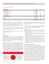
20092008
2007
200
8
2007
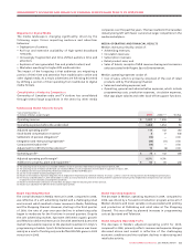
2009
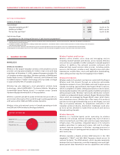
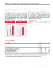
$3,948$3,809$3,558
CABLE TOTAL REVENUE
(In millions of dollars)