Rogers 2008 Annual Report Download - page 43
Download and view the complete annual report
Please find page 43 of the 2008 Rogers annual report below. You can navigate through the pages in the report by either clicking on the pages listed below, or by using the keyword search tool below to find specific information within the annual report.-
 1
1 -
2
-
3
-
4
-
5
-
6
-
7
-
8
-
9
-
10
-
11
-
12
-
13
-
14
-
15
-
16
-
17
-
18
-
19
-
20
-
21
-
22
-
23
-
24
-
25
-
26
-
27
-
28
-
29
-
30
-
31
-
32
-
 33
33 -
 34
34 -
 35
35 -
 36
36 -
 37
37 -
 38
38 -
 39
39 -
 40
40 -
 41
41 -
 42
42 -
 43
43 -
 44
44 -
 45
45 -
 46
46 -
 47
47 -
 48
48 -
 49
49 -
 50
50 -
 51
51 -
 52
52 -
 53
53 -
54
-
55
-
56
-
57
-
58
-
59
-
60
-
61
-
62
-
63
-
64
-
65
-
66
-
67
-
68
-
69
-
70
-
71
-
72
-
73
-
74
-
75
-
76
-
77
-
78
-
79
-
80
-
81
-
82
-
83
-
84
-
85
-
86
-
87
-
88
-
89
-
90
-
91
-
92
-
93
-
94
-
95
-
96
-
97
-
98
-
99
-
100
-
101
-
102
-
103
-
104
-
105
-
106
-
107
-
108
-
109
-
110
-
111
-
112
-
113
-
114
-
115
-
116
-
117
-
118
-
119
-
120
-
121
-
122
-
123
-
124
-
125
-
126
-
127
-
128
-
129
-
130
-
131
-
132
-
133
-
134
-
135
-
136
 |
 |

ROGERS COMMUNICATIONS INC. 2008 ANNUAL REPORT 39
MANAGEMENT’S DISCUSSION AND ANALYSIS OF FINANCIAL CONDITION AND RESULTS OF OPERATIONS
in Newfoundland and Labrador, and New Brunswick are served
by local head-ends. Cable’s two regional head-ends in Toronto,
Ontario and Moncton, New Brunswick provide the source for most
television signals used in the cable systems.
Cable’s technology architecture is based on a three-tiered structure
of primary hubs, optical nodes and co-axial distribution. The pri-
mary hubs, located in each region that it serves, are connected by
inter-city fibre-optic systems carrying television, Internet, network
control and monitoring and administrative traffic. The fibre-optic
systems are generally constructed as rings that allow signals to
flow in and out of each primary hub, or head-end, through two
paths, providing protection from a fibre cut or other disruption.
These high-capacity fibre-optic networks deliver high performance
and reliability and generally have capacity for future growth in the
form of dark fibre and unused optical wavelengths. Approximately
99% of the homes passed by Cable’s network are fed from pri-
mary hubs, or head-ends, which on average serve 90,000 homes
each. The remaining 1% of the homes passed by the network are
in smaller and more rural systems mostly in New Brunswick and
Newfoundland and Labrador that are, on average, served by
smaller primary hubs.
Optical fibre joins the primary hub to the optical nodes in the cable
distribution plant. Final distribution to subscriber homes from opti-
cal nodes uses co-axial cable with two-way amplifiers to support
on-demand television and Internet service. Co-axial cable capac-
ity has been increased repeatedly by introducing more advanced
amplifier technologies. Cable believes co-axial cable is a cost-effec-
tive and widely deployed means of carrying two-way television and
broadband Internet services to residential subscribers.
Groups of an average of 437 homes are served from each optical
node in a cable architecture commonly referred to as fibre-to-the-
feeder (“FTTF”). The FTTF plant provides bandwidth up to 860 MHz,
which includes 37 MHz of bandwidth used for “upstream” trans-
mission from the subscribers’ premises to the primary hub. Cable
believes the upstream bandwidth is ample to support multiple
cable modem systems, cable telephony, and data traffic from inter-
active digital set-top terminals for at least the near-term future.
When necessary, additional upstream capacity can be provided by
reducing the number of homes served by each optical node, which
is referred to as node-splitting. Fibre cable has been placed to per-
mit a reduction of the average node size from 437 to 350 homes by
installing additional optical transceiver modules and optical trans-
mitters and return receivers in the head-ends and primary hubs.
Cable believes that the 860 MHz FTTF architecture provides suf-
ficient bandwidth to provide for television, data, voice and other
future services, high picture quality, advanced two-way capability
and network reliability. This architecture also allows for the intro-
duction of bandwidth optimization technologies, such as switched
digital video (“SDV”) and MPEG4, and offers the ability to continue
to expand service offerings on the existing infrastructure. SDV has
been successfully deployed in head-ends serving over 60 percent of
Ontario homes. In addition, Cable’s clustered network of cable sys-
tems served by regional head-ends facilitates its ability to rapidly
introduce new services to large areas of subscribers. In new con-
struction projects in major urban areas, Cable is now deploying a
cable network architecture commonly referred to as fibre-to-the-
curb (“FTTC”). This architecture provides improved reliability and
reduced maintenance due to fewer active network devices being
deployed. FTTC also provides greater capacity for future narrow-
cast services.
Cable’s voice-over-cable telephony services are offered over an
advanced broadband IP multimedia network layer deployed across
the cable service areas. This network platform provides for a scalable
primary line quality digital voice-over-cable telephony service utiliz-
ing Packet Cable and Data Over Cable Service Interface Specification
(“DOCSIS”) standards, including network redundancy as well as
multi-hour network and customer premises backup powering.
To serve telephony customers on circuit-switched platforms, Cable
co-locates its equipment in the switch centres of the incumbent local
phone companies (“ILECs”). At December 31, 2008, Cable was active
in 179 co-locations in 63 municipalities in five of Canada’s most popu-
lous metropolitan areas in and around Vancouver, Calgary, Toronto,
Ottawa and Montréal. Many of these co-locations are connected to
its local switches by metro area fibre networks (“MANs”). Cable also
operates a North American transcontinental fibre-optic network
extending over 21,000 route kilometres providing a significant North
American geographic footprint connecting Canada’s largest markets
while also reaching key U.S. markets for the exchange of data and
voice traffic. In Canada, the network extends from Vancouver in the
west to St. John’s in the east. Cable also acquired various competitive
local exchange carrier (“CLEC”) assets of Futureway Communications
Inc. (“Futureway”) in the Greater Toronto Area during 2007. The assets
include local and regional fibre, transmission electronics and systems,
hubs, points of presence (“POPs”), ILEC co-locations and switching
infrastructure. Cable’s network extends into the U.S. from Vancouver
south to Seattle in the west, from the Manitoba-Minnesota border,
through Minneapolis, Milwaukee and Chicago in the mid-west and
from Toronto through Buffalo and Montréal through Albany to
New York City in the east. Cable has connected its North American
network with Europe through
international gateway switches in
New York City, London, England,
and a leased trans-Atlantic fibre
facility.
Where Cable does not have its
own local facilities directly to a
business customer’s premises,
Cable provides its local services
through a hybrid carrier strategy
utilizing unbundled local loops
of the ILECs. Cable has deployed
its own scalable switching and
intelligent services infrastructure
while using connections between
its co -loc ated equipment and cus-
tomer premises, provided largely
by other carriers.
CABLE’S STR ATEGY
Cable seeks to maximize subscribers, revenue, operating profit, and
return on invested capital by leveraging its technologically advanced
cable network to meet the information, entertainment and commu-
nications needs of its residential and small business customers, from
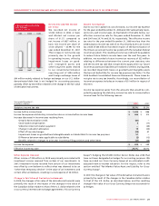
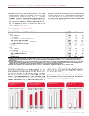
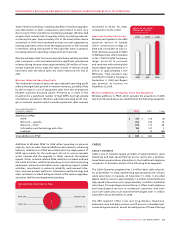
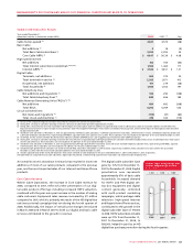
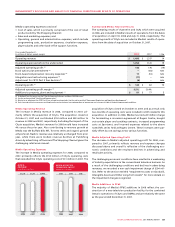
20082007
$3,809$3,558$3,201
CABLE TOTAL
REVENUE
(In millions of dollars)
2007
2008
2006